Background of the project
Roland Kossel of TLK Thermal Power Company and Nils Christian Strupp of the Thermal Power College of Braunschweig University of Technology used the TISC simulation environment to realize the joint simulation of each sub-model of the automotive air-conditioning system based on Dymola and TIL libraries, and analyzed the coupling simulation. influences.
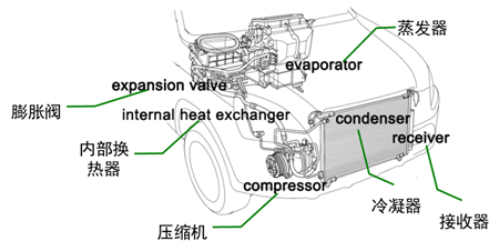
As shown in the above figure, the car's air conditioning system (HVAC unit) consists of five parts: a compressor, a condenser, a receiver, an expansion device, an evaporator and an internal heat exchanger.
The working principle of the air conditioning system: the circulating refrigerant is compressed into a high pressure after entering the compressor, and the temperature rises. The refrigerant then enters the condenser and releases heat to the environment. The refrigerant is further cooled in the heat exchanger by releasing heat to the low pressure side. Then, after expansion through an expansion valve mechanism (such as an expansion valve), it enters a low pressure. The refrigerant passes through the evaporator and evaporates. During the evaporation process, the refrigerant absorbs heat from the cabin and reduces the temperature inside the cabin. Finally, at the low pressure end of the heat exchanger, the refrigerant reheats into the compressor after it has overheated.
Project proposals
Use the TIL library and Dymola to build a closed loop system for automotive refrigeration cycles and run the simulation. The original closed-loop system is divided into sub-modules, and the coupling simulation between sub-modules is done based on TISC, and the characteristics of the two simulation modes are compared and analyzed.
The R134a evaporation cycle system was established, and each component was first modeled. The condenser is a flat tube heat exchanger with a refrigerant flow path. The four flow paths are divided into five control volumes. Since the receiver is integrated into the condenser, this component is also called the condensing receiver, as shown in the figure below. The evaporator model is similarly constructed and is divided into two layers with 3 channels per layer. Each channel is divided into 5 chambers.
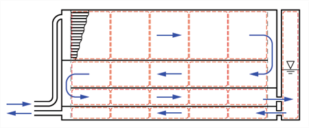
Schematic diagram of the condenser
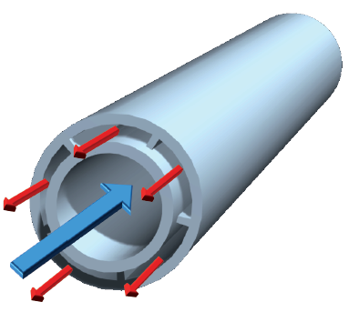
The heat exchanger model is a section of pipeline in which five chambers are routed in each section of the pipeline heat exchanger, as shown in the following figure.
The compressor model is a proposed constant model, which is used to describe the efficiency of the compressor by three efficiency equations: nominal volumetric efficiency, effective entropy efficiency, and isentropic compressor efficiency.
The isentropic expansion valve is modeled using the Bernoulli equation, which is suitable for fluids that are compressible and incompressible.
The figure below shows the closed-loop refrigeration cycle structure. The four colors represent four coupling models: the compressor, the high-pressure side of the condensing receiver and heat exchanger, the expansion valve, the evaporator and the low-pressure side of the heat exchanger.
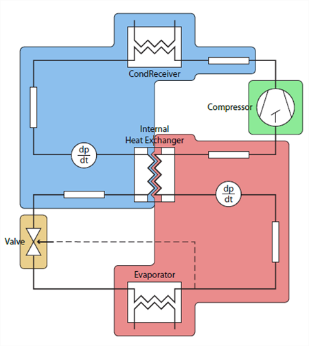
Closed loop refrigeration cycle structure
The interface after the heat exchanger is split is shown in the figure below: the resistance is set to extend the time constant of the system, and the capacitor is to consider the manufacturing temperature state.
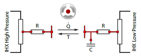
Heat exchanger interface structure
Implementation Effect
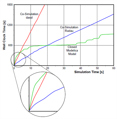
The comparison between the Dymola model simulation and the TISC-based split Dymola submodel simulation results.
â—Computation time comparison
â—† After the model is initialized, if the appropriate solution algorithm is selected, the calculation speed of the joint simulation has obvious advantages, which will exceed the speed of the closed-loop simulation.
â—† During the experiment, it was also found that the setting of the interaction step has a great influence on the simulation time.
â—† Co-simulation has more reliable calculations for different initial value settings, which can also save model development time to some extent.
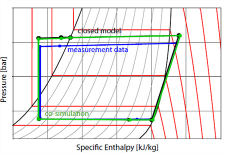
â—Computation result comparison
The results of closed-loop simulation and coupled simulation are consistent, and there is a certain error with the experimental measurement data. This shows that the simulation of the same model after splitting does not affect the calculation accuracy.
Project value
â— After splitting the closed-loop system model based on Modelica, the method of joint simulation using TISC is feasible.
â— Distributed coupling simulation after complex system model splitting can improve simulation efficiency and shorten simulation time. On the other hand does not affect the simulation accuracy
Led Facial Mask,Led Face Mask,Led Facial Mask For Home,Led Therapy Facial Mask
Zhongshan Okay Technology Co., Ltd , https://www.okaygroup.com