Application of hydraulic technology in steel drum machinery (2)
Xi'an Machinery Research Institute Jing Zhiping
Figure 3 is the hydraulic schematic diagram of the XJY28 steel drum bottom cover automatic stamping production line developed by our company in 1985. The production line uses the coil material to realize the unwinding, leveling, conveying, stamping, finished product transportation and waste disposal in the automatic stamping process of the steel drum bottom cover. The production line uses photoelectric length measurement and microcomputer control. The three-column stacking valve group on the left side of Fig. 3 is used to lift the coil placed on the lifting platform of the winder to the center height of the winder, push it onto the clamping shaft and open the clamping device to support the coil. The fourth column of the stacking valve from the left is used to generate the positive pressure of the roller feed required to send the coil to the press and the stamped scrap to the shearer. The fifth column of the valve block is used to overcome the braking inertia required for the feed inertia during the press feed in place. The sixth and seventh column valves respectively control the speed and synchronization of the coil and scrap conveying movement before and after the press, and the conveying movement of the coil and scrap with the leveling machine and the working rhythm of the press. The three-row stacking valve group on the right side of Figure 3 is used to invert the finished bottom cover of the press to the finished conveyor rack, drive the fixed-length conveyor of the step-type finished conveyor, and lift the steel to the top of the finished conveyor. The bottom cover of the bucket is dropped to achieve quantitative stacking. The system features a medium and low pressure 6.3MPa double vane pump and IS04401 international standard series superimposed valve to form a centralized control system. The function of the accumulator is different from the energy saving acceleration of the general system, and it is mainly used to improve the pressure stability during the coil conveying process. Another feature of the system is that the transmission power is small. The presses, levelers and scrap shears of the production line are mechanically driven. The roll and conveyor use the centralized control hydraulic drive system shown in Figure 3, with a total power of only 4kw, which is about one-tenth of the press.
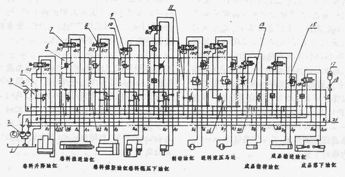
Figure 3 Hydraulic system diagram of automatic stamping production line for steel drum bottom cover

Figure 4 Hydraulic system diagram of the roll leveler
Figure 4 shows the hydraulic principle of the roll leveling unit designed by our company in 1994. The characteristics of the system are similar to those of the automatic production line of Figure 3, mainly for the leveling machine to replace the traditional mechanical transmission with a hydraulic transmission with stepless speed regulation. This not only eliminates the troublesome clutches and brakes in the leveler, but also adapts to the press, the winder and the coil conveyor of different working beats, so that the leveler can be easily synchronized with it.
Figure 5 and Figure 6 are the hydraulic schematic diagrams of the XJY48 and XIi 48A pre-rolling machines developed by our company in 1990 and 1992 respectively. The former is characterized by dividing the pre-rolling and spraying into two stations and adopting an AC wet-type reversing valve with a high commutation speed to improve the production cycle. The latter combines pre-rolling and spray-bonding into one station and uses a dual pump to separate the main motion (bottom cover rotation) and auxiliary motion (pre-roller feed) transmissions.
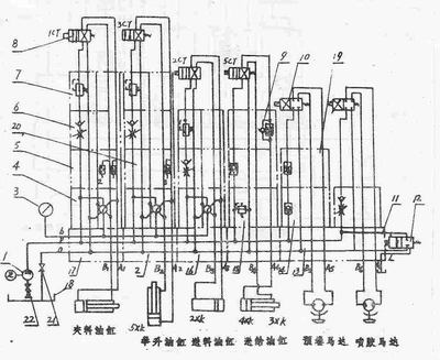
Figure 5 XJT48 pre-rolling machine hydraulic system diagram
Figure 7 shows the hydraulic schematic of the XJY49 adjustable universal crimping machine developed by our company in 1992. This system can be used as a more complicated and comprehensive example of the technology used in hydraulic machinery in barrel making machines. The system is designed using the IS04401 international standard. The power source consists of two high pressure double vane pump units 4 and 2. The main pump 4 is used to drive the spindle rotation and sealing movement of the main hydraulic device, and the auxiliary pump 2 is used to drive the auxiliary movement of the machine such as feeding and curl feeding. Through the spindle section selection knob on the machine control console, a double unloading or two simultaneous operation of the double main pump 4 can be performed simultaneously, so that the spindle is at a low speed (60-280r/mln) or high speed (60-360r/min). ) Section work to choose. In the low speed or high speed section, the speed control valve 22 can be used for stepless speed regulation of the spindle operation. This gives the machine the ability to select the optimum spindle speed for different material thicknesses, barrel diameters, materials and production beats to achieve the desired hemming quality. The maximum torque of the spindle can be set by the superimposed electromagnetic spill valve 24 on the hydraulic motor circuit. The valve also allows the main pump 4 to be unloaded in situ to maintain oil pump life and reduce system heating. The relief valve 23 is used to control the braking force of the hydraulic motor.
The pressure at which the seal is clamped is set by the pressure reducing valve 20 on the circuit and is held by the pilot operated check valve 39. The high speed movement speed of the seal empty stroke can be adjusted by the one-way throttle valve 35 on the circuit. The slow feed rate near the sealing position is adjusted by the electromagnetic throttle valve 19. The synchronization of the left and right sealing movements is regulated by the synchronizing valve 38.
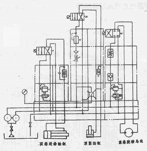
Figure 6 XJY48A pre-rolling machine hydraulic system diagram
The four-column stacking valve group in the right part of Fig. 7 constitutes a multi-power component anti-interference centralized control system for controlling the feeding of the machine tool and the feeding motion of the six crimping feed power heads. The large flow P oil path and the small flow rate P of the double vane pump 2, when the oil path is in the home position of the machine, respectively, are flowed back to the fuel tank through the respective >d1 electromagnetic unloading valves 28 and 9 to realize the in-situ unloading. When the feed cylinder or each of the hemming feed cylinders are in the idle stroke movement, the P oil passage and the P1 oil passage are simultaneously driven by the oil supply due to the low pressure required by the system and the set pressure of the P oil passage electromagnetic spill valve 28 is not reached. The crimping feed member approaches the working position at a high speed. When the working position is reached, the buffer command throttles the electromagnetic throttle valve 34 or the electric speed regulating valve 30 in the oil passage to decelerate the power component. In the three sets of crimping feed cylinders, since the high and low speed feeds of the respective groups of cylinders are crossed, the pressure state is complicated. The fast movers in the three groups of cylinders are supplied with oil from the P oil passage and the Pl oil passage. At the same time, the low-speed athletes are respectively subjected to the inlet throttle and the outlet throttle deceleration of the cylinder by the external control sequence throttle valve 31 and the electric speed control valve 30, respectively. The electric speed regulating valve 30 is mainly used to ensure the stability of the feed speed when the load changes, and the working feed stroke can be shortened to improve the machine tool productivity. The external control sequence throttle valve 31 is a key component for realizing the high and low speed cross feed of the three groups of cylinders without mutual interference. In the three sets of crimping feed cylinders, the synchronization of the left and right feed movements of each group is regulated by the synchronizing valves 37 on the respective oil passages. The sequence valve 29 can replenish P and the excess pressure oil of the oil passage to the P oil passage for high-speed movement.
Hydraulic drive technology has become one of the fastest growing technologies in mechanical equipment. It has also been widely used in barrel making machinery. As with all science and technology categories, the application of hydraulic technology cannot be perfect. Many intertwining problems, such as media leakage and purification, medium compressibility, and limitations on the accuracy of the transmission, require sufficient attention in the design, manufacture, and use of hydraulic machinery. It is conceivable that with the rapid development of the barrel industry in the 21st century, the depth and breadth of hydraulic transmission technology in the field of barrel machinery will be significantly improved.
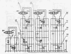
Figure 7 Hydraulic system diagram of adjustable universal crimping machine (partial)
Automatic Sensor Sanitizer Dispenser
We are the company specializing in manufacturing hotel supplies. Main products are hand push soap dispensers, automatic Sanitizer Dispensers, paper dispensers, hand dryers, hair dryers, Trash Bins, etc. Most of our products have certificates like CE, UL, GS, ROHS. With moulding workshop in house and experience techinicians, we accept OEM ODM products.
wall mount dispensers,standing dispensers,table top dispensers,Foam Soap Dispenser
TAISHAN YUEXIN INDUSTRIAL GROUP LIMITED , https://www.gdmetalproducts.com